A Beginners Guide to Patch Bays
Patch bays allows us to route multiple pieces of outboard gear in one signal chain, while also allowing for us to create complex signal chains. Rather than climb behind your desk to rearrange your cables before every session, patch bays allow for quick & simple connections without demanding as much time. Not only do they improve studio efficiency but they also make our studios look much tidier with fewer to no cables having a free party!
What is a Patch Bay Used For?
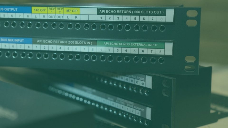
We would use a patch bay to control and create signal chains via inputs and outputs from devices connected to it. A patch bay usually comes in rack format which allows us to mount it on the same rack as our other outboard gear from delay, reverb, EQ, and compression hardware, as well as filters and mic preamps!
Outboard gear always connects to the back of your patch bay and we use patch cables on the front of the patch bay to direct the signal flow from one piece of gear to another.
At the beginning of our signal chain could be our audio interface which is receiving audio from our DAW or our synth and/or microphone, and from the interface, the signal travels into the back of the patch bay. Once in the patch bay, and depending on the order you’ve patched each piece of outboard gear on the front of your patch bay, your outboard gear will then begin processing your signal in the signal chain you’ve set up.
So, with this example, your signal travels from your synth into your interface (1) (and DAW) and then into your delay unit (1), then into your patch bay (2) then through your outboard compressor unit and back into the patch bay (3), into an outboard EQ unit and back into the patch bay (4), and so on…
Alternatively, you could route your microphone or synthesizer directly into the patch bay and begin processing that signal directly. This eliminates the need for an audio interface and/or DAW altogether!
What Are The Different Types of Patch Bays?
We define different types of patch pays by their normalling capabilities as well as what patches they accept.
“Normalling” refers to how the patch bay in question organises signal flow in and out of itself. Some patch bays like the Art Pro Audio P48 allow you to control which method of normalling they use while others have only one specific method of normalling.
“Patches“, on the other hand, refers to jack type on the front and rear of your patch pay. The two most common types are 1/4″ type TRS patch bays and TT type TRS patch bays, but there are also XLR patch bays too!
For a home studio, a TRS patch bay is our recommendation. TT (tiny telephone) patch bays may require soldering to connect devices to the back of the patch bay, while TRS patch bays are also cheaper!
XLR patch bays allow you to connect jacks on their rear inputs/outputs to the top row of inputs on the rear of your 1.4″ TRS patch bay, providing that you have a female XLR to 1/4″ TRS cable.
Be mindful of phantom power should you connect a microphone to your patch bay. Most patch bays accommodate for phantom power travelling through their circuitry, but not all will cope. For more information, check out this article by Sound on Sound.
As for balanced and unbalanced connections: the only issue to be wary of should you plug an unbalanced signal into a balanced jack is that the signal will remain unbalanced. But with balanced gear and the use of a 1/4″ TRS cable, the signal chain will be balanced through and through.
Now, let’s talk about normalling!
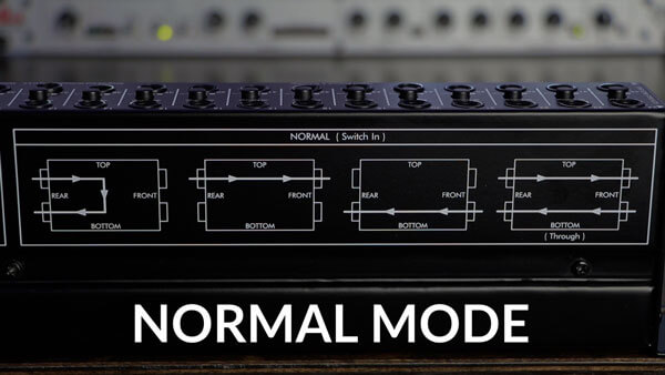
Normal/Full-Normal Patch Bays
A normal/full-normal patch bay requires you to run outboard gear into the top row of the rear inputs. From here, the signal automatically runs to the bottom rear output below the rear input. From here you can route the output into the next input, and so on.
However, should you connect a patch cable to the front output (top) or front input (bottom) then the signal no longer runs to the rear output and routes straight into the patch cable and sends the signal to wherever you route the patch cable!
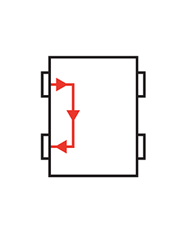
Should you connect a patch cable to the front input (bottom), the signal will run straight to the rear output (bottom).
Half-Normal Patch Bays
In the same way that a normal patch bay does, a half-normal patch bay routes the signal from the rear input into the rear output. The difference is that when a patch cable is connected to the front output (top row)… the signal remains routed to the rear output! This allows you to carry out the signal chain without adding any processing via patch cables rather than using the rear inputs and outputs.
However, when you connect a patch cable to the front input (bottom row) the link between the rear input and output breaks.

This setup is useful for monitoring wet/dry recordings which means monitoring an unprocessed signal (dry) and the same signal when it post-processing (wet).
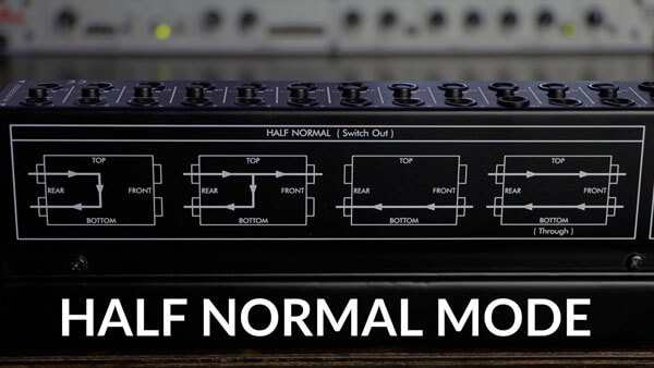
Again, connecting a patch cable to the front input (bottom) will route the signal directly to the rear output (bottom).
Non-Normal/De-Normal Patch Bays
A non-normal patch bays have no predetermined signal routes. Points are only routed to one another when a patch cable has physically routed them. This offers the most flexibility to you but is also the most time consuming of patch bays.
Are you looking for some new and energising sounds to run through your DAW? Looking to add your own twist to a ready-made sample via your own signal chains?
You’re in the right place. Mixxed has thousands of samples for you to manipulate and add to your killer beats. Ranging from bass; drums and percussion; vocals, pads; leads; synths; brass; keys; acoustic and electric guitars… and so much more. Download anything your ears crave for less than $3 a month!
Sign up today to give your listeners the ultimate music experience!