Explain Compression: What are the Different Types of Compressors?
Did You Know There Are Different Types of Audio Compressors?
Welcome to the final article in our Explain Compression series!
If you’re just tuning in, check out our previous articles here:
Explain Compression
How Do Compressors Work?
5 Types of Compression and When to Use Them
What is Compression Used For?
Top 5 Compressor Plugins to Help You Control Dynamics
We’ve discussed how audio compressors work, why audio compression is needed, and what audio compression is used for. Now it’s time to explore the types of audio compressors that are available today and how they function. But to give you the clearest understanding of the electronic analogue madness we’re about to talk about, we wanted to explore some important points that define compressors.
What’s the Difference Between Feedback and Feedforward Topologies?
A topology in electronic circuits is, on a very basic level, the map and direction of the electrical current in that circuit.
With compressor topologies, we need 4 basic elements that we’ve discussed before: input, output, gain reduction and sidechain.
Input = input signal, pre-compression
Gain reduction = component that controls the dynamic range of a signal, responsible for compression.
In this article, the gain reduction component is the focus point. They vary depending on what compressor you’re using… either a tube, field effect transistor, light dependant resistor, voltage controlled amplifier, diode bridge or a pulse width modulator. Obviously, we’re going to get into all of these.
Sidechain = signal that controls/influences the gain reduction element
The sidechain is either the input signal or a duplicate of the input signal, unlike sidechain compression as a method itself where the sidechain is another method entirely.
Output = output signal, post-compression
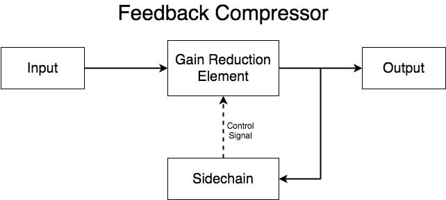
What’s feedback compression? Feedback compression is when the sidechain element is placed after the gain reduction element. This means feedback compressors can’t analyse the input signal before the gain reduction element does its thing.
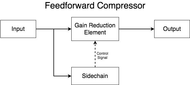
What’s feedforward compression? Feedforward compression is when the sidechain element is placed before the gain reduction element. This allows feedforward compressors to analyse the input signal amplitude and adjust the sidechain signal before it reaches gain reduction. This is what enables a lookahead parameter on some plugins.
Feedforward topologies are great for transient sounds because it calculates the amplitude of the incoming signal and how much it should be compressed.
What is Peak Compression?
Peak compression is when the compressor reacts to the peak of the input/sidechain input. This means it reacts to the highest point in amplitude. When the signal breaches the threshold, the compressor kicks in.
Peak compression has been the foundation of our Explain Compression Series and will continue to be, but RMS compression is handy knowledge for you to know.
What is RMS Compression?
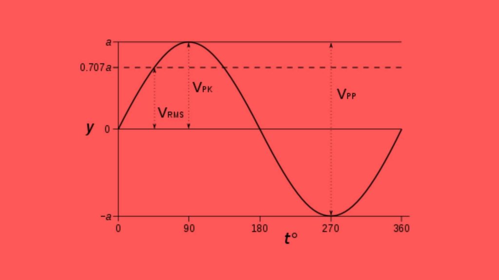
RMS (root mean square) compression is when the compressor reacts to the calculated average loudness of the input/sidechain signal. When this average amplitude exceeds the threshold, the compressor kicks in.
The RMS of a signal is the mathematically calculated average of the total amplitude of a signal over time, not the actual amplitude.
RMS always refers to the strength of a signal level. It could refer to any of the following: voltage, power, dBFS or any other units that refer to the strength of signals or a devices’ capability of handling said strength.
With compressors, it refers to the compressors ability to meter its sidechain signal.
Sine waves have an actual average amplitude of zero because the amplitude is even in both positive and negative amplitude values.
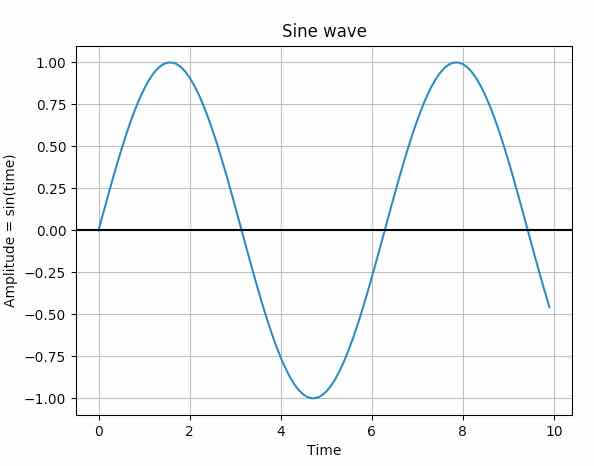
However, its RMS value is 0.707x the peak value.
What is an Upward Compressor?
Available in digital and analogue compressors, as well as being achievable via parallel compression, upward compressors boost the amplitude of a signal that sits below a set threshold and keeps the amplitude the same above the threshold.
To explain this, we want you to take everything you learned about ratios in our first article and flip it.
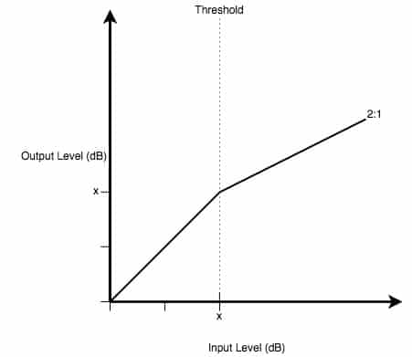
Above is a standard 2:1 ratio on a compressor, as we have explored before.
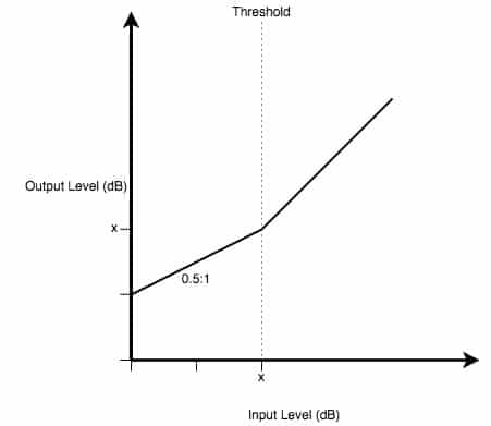
However, the above is an example of upwards compression. 0.5 is the inverse of 2, and you can see the level of amplification is equal to the level of attenuation in the first diagram.
Now, onto the good stuff!
Types of Audio Compressors and Their Applications
Compressor Plugins
Up first, we’re going to jump into the digital realm.
Probably the most common compressor known amongst budding producers, compressor plugins are pieces of software that use binary code (1’s & 0’s) to produce dynamic range compression effects with digital audio signals – usually inside a DAW.
Compressor plugins are a mixed bag. You will find entirely new, innovative, compressor plugins that are made to be their own thing.
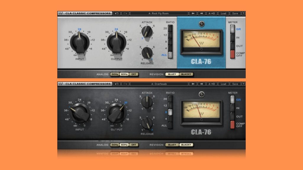
On the flip side, you will also find compressor plugins that have been made to emulate real hardware. Waves, for example, recreated the Universal Audio 1176 compressor (a FET compressor, which we’ll discuss later) as a digital plugin: CLA-76 Compressor.
Another great example is the Fairchild 660/670 Compressor, which is a tube compressor (more on these later too), which has been recreated as a digital compressor plugin by Waves: the PuigChild Compressor.
All DAW’s have their own stock compressors. Some have limited capability, but some have a lot of variety in options. But you should know there are lots of third-party compressor plugins on the market.
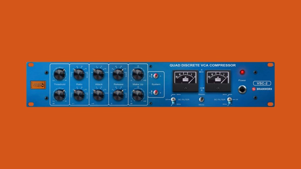
What Are VCA Compressors?
Analogue voltage controlled amplifiers (VCA) compressors split the input signal into a “detector path” (which is what controls the compression) and an output path.
With low levels of distortion and offering you full control over its parameters such as attack and release, VCA compression gives you the ultimate transparent sound. However, it’s important to note that when the control voltage changes it can leak into the output signal. This usually doesn’t cause any noticeable issues, but it can sometimes add noticeable colouration to your sound.
Along with FET compressors, VCA compressors are some of the most popular compressors out there.
You can manipulate the detector path with your compressor parameters, and the detector path operates as the voltage controlled amplifier for the output path.
You can compare the detector path to a fader on a physical console. Once the input signal surpasses your threshold, the fader comes down.
Due to their transparent sound, they are perfect for high transient sounds like drums or synths. As well as this, they are a staple for mastering buses!
A renowned VCA compressor is the Brainworx Vertigo VSC-2.
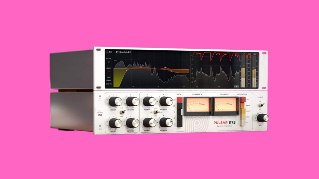
What is an FET Compressor?
FET compressors, also analogue, use field-effect transistors at the heart of their circuitry. Field-effect transistors use electric fields (a physical field that surrounds electrically charged particles) to control current flow.
FET compressors preserve transient information, which makes them very bright sounding, in an amazing fashion. They also offer speedy attack and release times.
This all makes them perfect for taming crazy sound sources like electric guitars, as well as nifty tools for parallel compression!
Transformers (devices used to change the voltage of electrical current, not Optimus Prime) are used to reduce the signal level before compression & offer a gain increase once the compression has finished. This, naturally, adds harmonic saturation.
FET compressors need a low level input signal but require more output gain. A drawback with this is that the noise floor can be raised. Curious how to deal with noise floor? Click here.
An example of a FET compressor in plugin form is the Pulsar Audio Pulsar 1178
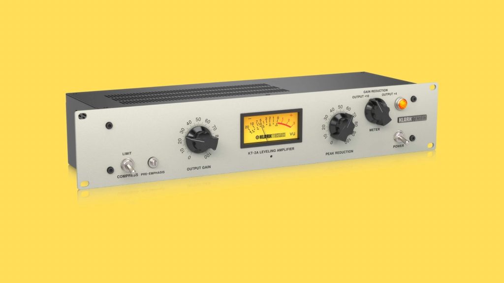
What is a Tube Compressor?
The first hardware compressors on the scene, analogue tube compressors usually have slow attack and release times with a soft knee, a ratio that increases when the signal amplitude increases (known as a program-dependent ratio), and a little harmonic distortion added in.
Tube compressors are analogue compressors centred around vacuum tubes (also known as valves).
Vacuum tubes control electrical current flow between electrodes (electrical conductors used for contact between non-metallic parts of circuits) inside the sealed vacuum. Triode tubes (a tube with three electrodes) control the rate of current flows with the additional electrode known as a “grid”.
When the input signal begins increasing, less current is sent to the grid, and so the overall signal level is reduced – which adds harmonic saturation.
The valve is the central element of a tube compressors compression circuit. Many compressors use tubes as a component, but mainly for makeup gain. Tube compressors are commonly used on mix/master buses because they add warmth via their harmonic saturation characteristics.
For a smashing tube compressor, look no further than the Klark Teknik KT-2A Tube Compressor
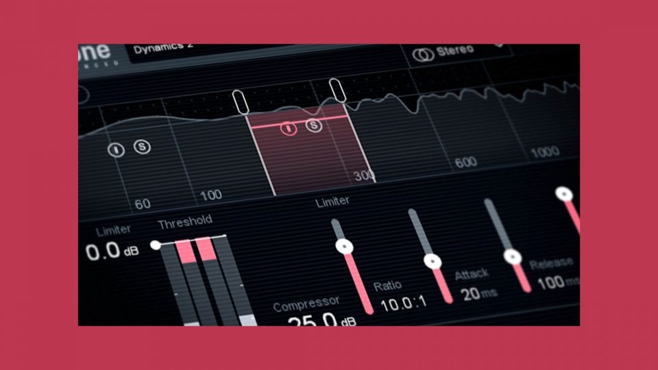
What Are Multiband Compressors?
We’ve discussed the multiband compression method before, but we can’t write an article about the different types of compressors and not bring it up.
Available as digital plugins and analogue hardware, multiband compressors split your audio signal into different frequency bands which you can individually control the dynamic range of.
Each frequency band has its own parameters that you can control like a standalone compressor for a complete signal. Multiband compression is a fantastic tool that allows you to dive deep and control the dynamic range of a sound like no other method of compression.
You can also crossover the different bands to bandpass filter individual bands. This, however, can create crossover distortion. Multiband compression allows for a more natural sound, but also allows you to dissect your sounds and eliminate elements of the sound that you don’t want.
The example we gave in our previous discussion was kick drums. If you have a lot of high end on your kick but want to preserve its punch, you can use a multiband compressor to eliminate the top end.
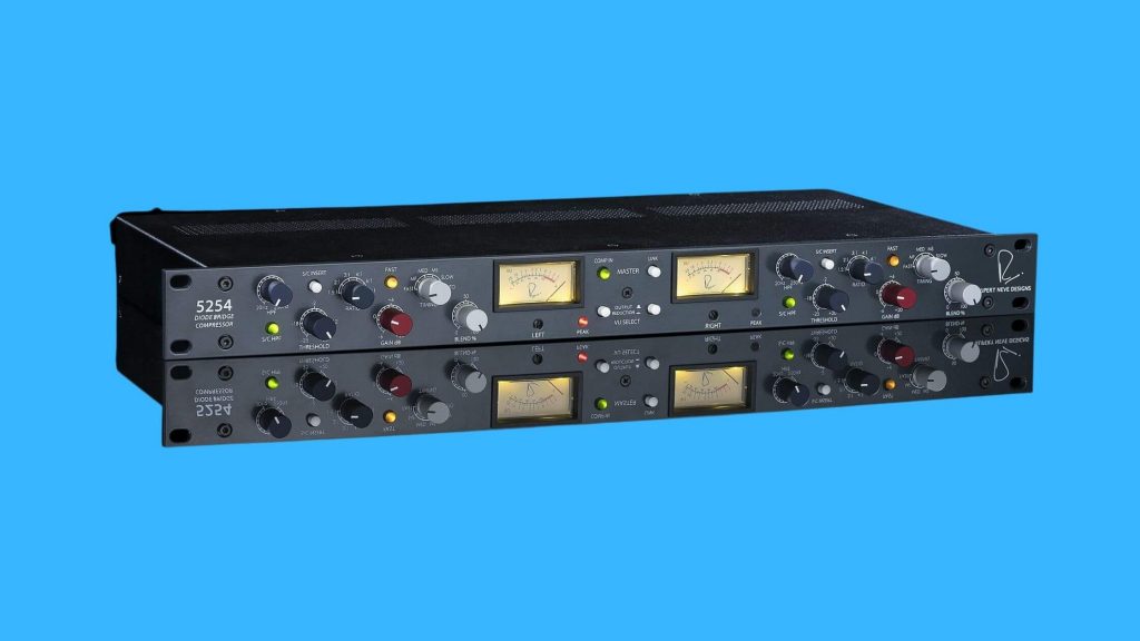
What Are Diode Bridge Compressors?
Analogue diode bridge compressors, also known as diode ring compressors, use two pairs of diodes that are set up in a diamond array. However, they are not limited to 4 diodes, more can be used.
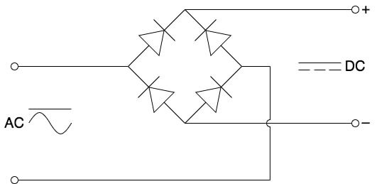
The audio signal is channelled through two opposite corners while the control signal is channelled across the other two.
Diode bridge compressors need high levels of output gain, but low levels of input gain.
A diode is a semiconductor that acts as a one-way switch that channels current. However, there is a small area at which its conductance varies compared to the voltage applied to it. This is why they can be used as voltage controlled attenuators.
To avoid a high level of distortion, all diodes must match and the signal being channelled must be balanced because of the pairs of diodes. The signal must also have a smaller dynamic range than you may usually apply to a compressor because of the diodes’ transfer curves (variation of the diode current versus the voltage across the diode). Basically, so you don’t burn them out.
Transformers are also used to set the levels of the control and audio signals which adds distortion to the signal – which the circuit itself also does. However, this distortion is actually harmonically rich and is pretty pleasant.
All of this means, however, that diode bridge compressors aren’t very popular… like, at all.
The Rupert Neve Designs 5254 is a leading diode bridge example.
What is a Pulse Width Modulation Compressor?
Pulse Width Modulation (PWM) alters the amplitude of a signal by reducing the average amplitude/power of the electrical signal it’s fed. These analogue compressors do this by cutting the signal up into discrete parts known as pulses, and the pulses play back very quickly. The fun part kicks in when you begin altering the width of these pulses over time. This is how we perceive the output signal is compressed.
The pulses are turning the signal on and off – which is what’s done at such a fast rate. The average value of the signal is what’s then outputted.
The width of the pulses is known as “duty cycle“. Duty cycle, basically, is the time duration of each pulse on and off time.
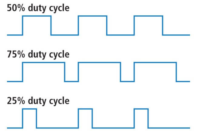
In the image above, you can see three examples. We’ll use the bottom one for our explanation.
You can see that it has a 25% duty cycle, and the “on” is smaller than the “off” section. As you have probably guessed, the “off” section is worth 75% when the “on” section is worth 25%. Now you can translate this to the other examples.
The longer the PWM is “on” more signal will pass through. Due to the quick duration that all of this is happening, there is no distortion or unwanted characteristics.
The parameters such as attack and release, ratio, threshold, and knee all control the pulse width modulation that gives you your duty cycles. This all means that PWM compressors can be the fastest compressors with no added distortion.
What is an Optical Compressor?
The last compressor on our list is the optical compressor!
Analogue optical compressors utilise light to compress the audio signal. I know, they’re pretty damn cool!
They use light dependent resistors (resistors reduce current flow) that provide high resistance when no light is shining on them and offer less resistance when light is shining on them. How much resistance they offer depends on the amount of light.
The input signal triggers a light that feeds the LDR’s, so when amplitude increases – more gain reduction kicks in.
Usually only used on single tracks rather than for bus compression, optical compressors add very little to no harmonic saturation (unless components like tubes are added to the circuitry). This makes them perfect for smoothing out sounds with few transients.
Where Does Compression Go in a Signal Chain?
You can make compression sound great on anything with the right use of parameters.
This means that there is no straightforward blanket answer to this question.
It can be a fantastic first process in a signal chain to make sure your amplitude levels are even, or it can be used at the end of your signal chain or even final mix down to glue things together or add some harmonic saturation.
Compression can go anywhere in a signal chain. It’s not black and white. It’s a creative tool as well as a mixing one.
It can be used before or after EQ’ing, or both if you’re feeling really experimental. It can be used after any process you undertake in your track.
Compression Explained
We did it! That’s compression in a nutshell. Now you should be entirely comfortable controlling the dynamic range of your tracks and music you’re creating with samples from Mixxed.
We have explored how compressor parameters work, the different methods of compression, what it’s used for and now we’ve finalised what type of compressors there are.
We hope you enjoyed this series and learned everything you needed and more.
See you next time!